ZX81 Composite Mod
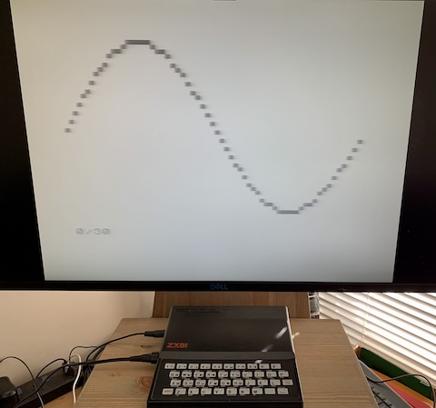
After my unexpected success with the hacked-together version of the ZX81 composite mod, I was keen to press on and do it properly. To skip to the end, it went pretty well, and I now have a usable ZX81:
As mentioned in the previous post, my ZX81 is a later version that generates a sensible video signal with back porch, so the mod is very simple — essentially just a transistor to amplify the ULA’s video output signal to the level needed for the external connection. The only question was how to fit it into the case. I wanted to leave the RF modulator as intact as possible (after all, the machine is an antique, so I feel like I should treat it with respect), so the basic idea is to disconnect the relevant lines but leave the components in place.
As to where the new components go, I’ve seen two options: put everything inside the RF modulator case, or keep it all outside, and route the necessary connections through. The first option looked ambitious: I wasn’t confident that I could work in such a confined area, and more importantly it involved cutting rather just desoldering the old connections, so would be harder to reverse. The second option has neither problem, but looked a bit messy.
Looking at the board, I came up with a compromise I was happy with: putting the transistor outside the modulator, with the collector and base soldered directly to the +5v and video signal connections previously used by the modulator, and the 100Ω resistor on the inside. One lead of the resistor is soldered to the modulator case for ground, and the other end is soldered to the pin of the RCA jack for output, and also routed through the insulated hole to connect to the emitter of the transistor.
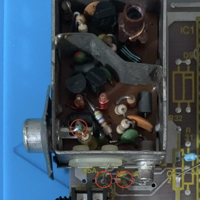
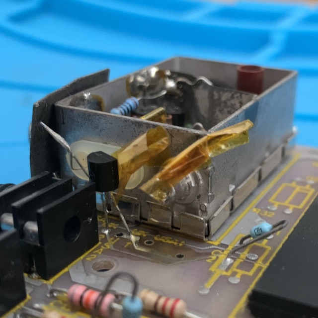
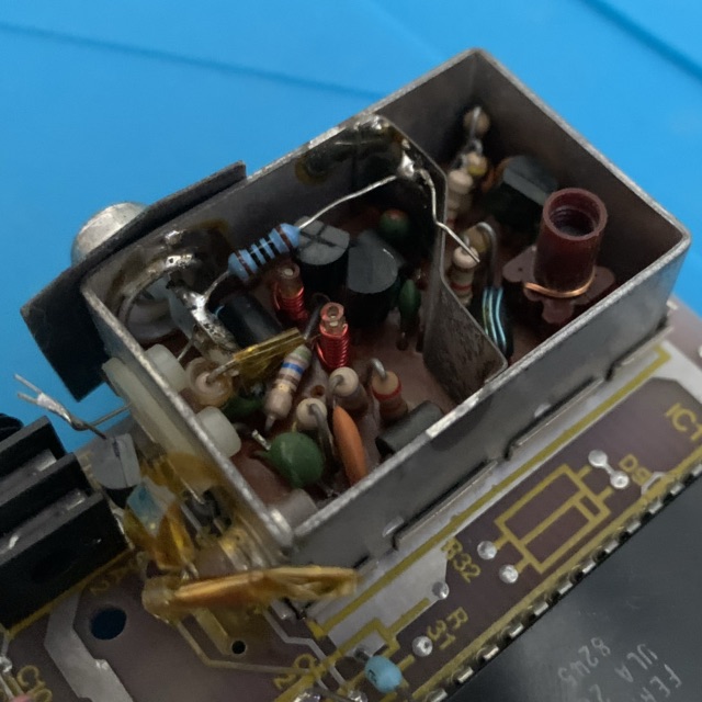
The above images show the changes. From left to right:
- The unmodified RF modulator. The three connections to be desoldered are marked with red circles.
- The modification, showing the video signal and +5v connections to the board.
- Another view of the modification, showing the resistor lead connecting to the RCA pin and out to the transistor.
The old connections are insulated yellow tape to avoid shorts. This is probably the messiest part of the project; otherwise, it’s pretty neat, and doesn’t get in the way once the cover is back on the modulator. Once I’d made the changes, I plugged in the board on its own to check the signal and got a recognisable but madly flickering picture, indicative of a loose connection. I redid the soldering on the RCA pin, tried again, and the picture was good. After reconnecting the keyboard ribbon (I’ve been lucky in that regard; it’s in amazingly good shape considering its age) and reassembling the case, I had a working ZX81 that could be used with a (relatively) modern display.
You may notice from photo at the top of the post that the image looks a bit washed out — the background is the expected light grey, but the “black” is very much not black. This is at least in part due to the cheap RCA-to-HDMI converter I’m using on my monitor; it looks better on a TV with built-in composite input. I tried adding additional resistors on the video output as described here, but they made the whole picture darker rather than increasing the contrast. I’m not sure if there are other things to try, or if that’s as good as the picture will get, but in any case it’s good enough for my purposes. Now I can start to explore the ZX81 itself.